Automated depletion zone division
Serpent 2 has the capability to perform automated depletion zone division for materials in burnup calculation. There are two options:
- The number of radial regions in 2D pin-type objects can be entered directly in the material card ("Serpent 1" type division).
- The div card can be used to perform 3D depletion zone division.
Both approaches are discussed below. With automated depletion zone division it important to always check the volumes using the Monte Carlo based volume checker routine, and if necessary, define the volumes manually.
Contents
Division with material card
Division with divisor card
The div card can be used to separate each cell into its own depletion zone, and further sub-divide pin-type objects into axial-, radial and angular sub-zones. The division takes into account the universe-based geometry structure, so the same cell in two different univeses is treated as two separate cells. For fuel assembly geometries, for example, each pin can be treated as a separate material. If the assembly is put in a core lattice, the same pin in two different assembly positions can be treated separately and so on.
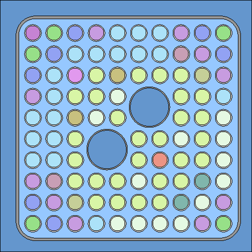
The basic methodology is best illustrated by an example involving a BWR fuel assembly geometry consisting of a 10 x 10 lattice of fuel pins with 13 different fuel types (fuel1, fuel2, ... fuel13):
Simple cell-based division
Defining a div-card for each fuel composition:
div fuel1 sep 1
div fuel2 sep 1
...
div fuel13 sep 1
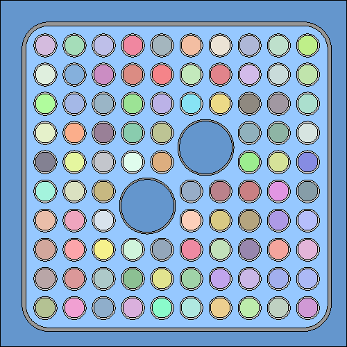
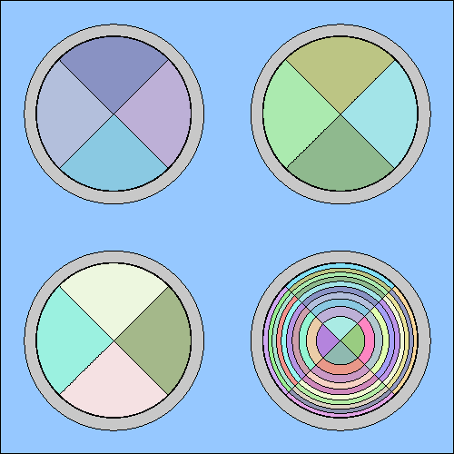
divides identical compositions into different depletion zones:
Some of the colors in the plot may appear similar, but each regions now contains a different material. The value after the sep-entry defines the geometry level at which the division is performed. Value 1 refers to the last level, which essentially means that all cells in the geometry are handled separately. The use of the sep entry is revisited at the end of this example.
Radial, angular and axial sub-division
Accounting for the depletion of burnable absorber requires radial sub-division, which for pin-type material regions can be done automatically. If it is assumed that the absorber is mixed in fuel types 9-13, sub-division into 10 rings can be done using the subr-entry:
div fuel9  sep 1 subr 10 0.0 4.38E-01
div fuel10 sep 1 subr 10 0.0 4.38E-01
div fuel11 sep 1 subr 10 0.0 4.38E-01
div fuel12 sep 1 subr 10 0.0 4.38E-01
div fuel13 sep 1 subr 10 0.0 4.38E-01
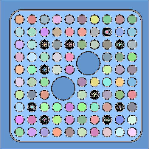
The division is made between 0 and 0.438 cm into 10 rings with equal cross-sectional area:
If necessary, the fuel pins can be further sub-divided into angular sectors using the subs-entry, for example:
div fuel1 sep 1 subs 4 45.0
div fuel2 sep 1 subs 4 45.0
...
div fuel13 sep 1 subr 10 0.0 4.38E-01 subs 4 45.0
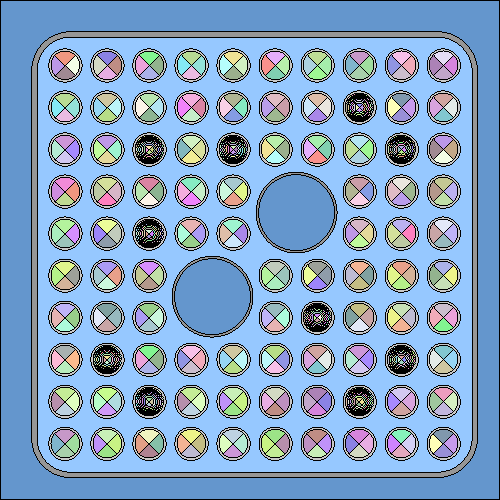
The pins are divided into 4 sectors and tilted by 45 degrees:
The axial division works in a similar manner using the subz-enetry, taking the number of axial zones and minimum and maximum coordinate as the input values. Radial, angular and axial sub-division are limited to pin-type material regions, but the cell-based division applies to any type of geometry.
Sub-division and geometry levels
In large complex geometries it may not be possible to handle every cell as a separate depletion zone. In such case the sep-entry can be used, for example, to sub-divide the fuel in a large LWR core into separate depletion zones on assembly-, instead of pin-basis. Another example is an HGTR geometry consisting of millions of individual fuel kernels. Instead of handling each kernel as a separate depletion zone, the division can be done based on compacts or pebbles. The following example is based on a pebble-bed HTGR geometry.
The concept of a geometry level may be a bit difficult to understand, but basically it means that whenever there is a cell, lattice, or any other geometry structure filled with another universe, it adds a new level in the geometry. What makes things a bit more complicated is that regular structures, such as lattices, also form a new level. So in a typlical BWR assembly geometry, for example, the levels are:
- Structures defining channel box wall, moderator channels, etc. and the outside world
- Lattice of fuel pins
- pin universes
The number "<lvl>" following the "sep" entry determines the number of levels counted backwards from the last one (<lvl> = 1 being the last). I decided to go with this approach instead counting forwards because in complicated geometries the different levels may be difficult to see, and it might be easier to start with <lvl> = 1 and increase the number until the geometry plotter shows the desired result.
Consider another example, consisting of 4 HTGR-type fuel pebbles filled with 50 TRISO particles each. The geometry consits of 5 levels:
0: a cube containing the pebbles 1: pebble distribution 2: pebble universes 3: particle distributions 4: particle universes
With "div sep 1", the division is based on particle universes (level 4), and each particle in each pebble is handled as a separate depletion zone, resulting in a total of 200 burnable materials. A geometry plot shows each fuel kernel in different color:
Things to note
- When the divisor card is used, Serpent tries to calculate the sub-zone volumes automatically. Since this may fail, it is always a good idea to check the volumes using the Monte Carlo based volume checker routine, and if necessary, define the them manually.
